–
If you want to get good at weld fixture or assembly fixture design, you need to get very familiar with dimensioning holes and features on angled surfaces.
Detailing Features on Angled Cuts.
Of course, your first duty is to learn or know where to find your company’s standards for dimensioning angled surfaces and the features on them. If you don’t have standards to refer to, then read on. Here are some dimensioning practices I have observed…
Dimensioning the Angled Surface
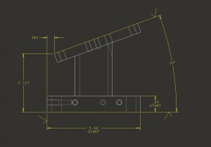
Some companies dimension angled surfaces using … well… angles.
NOTE: You can double click on these images to get a bigger and clearer view.
In the image above the edge of the angled surface is defined by dimensions from the starting finished surfaces. Then an angle dimension (20 degrees) is given.
Dimensioning the Features on the Angled Surface
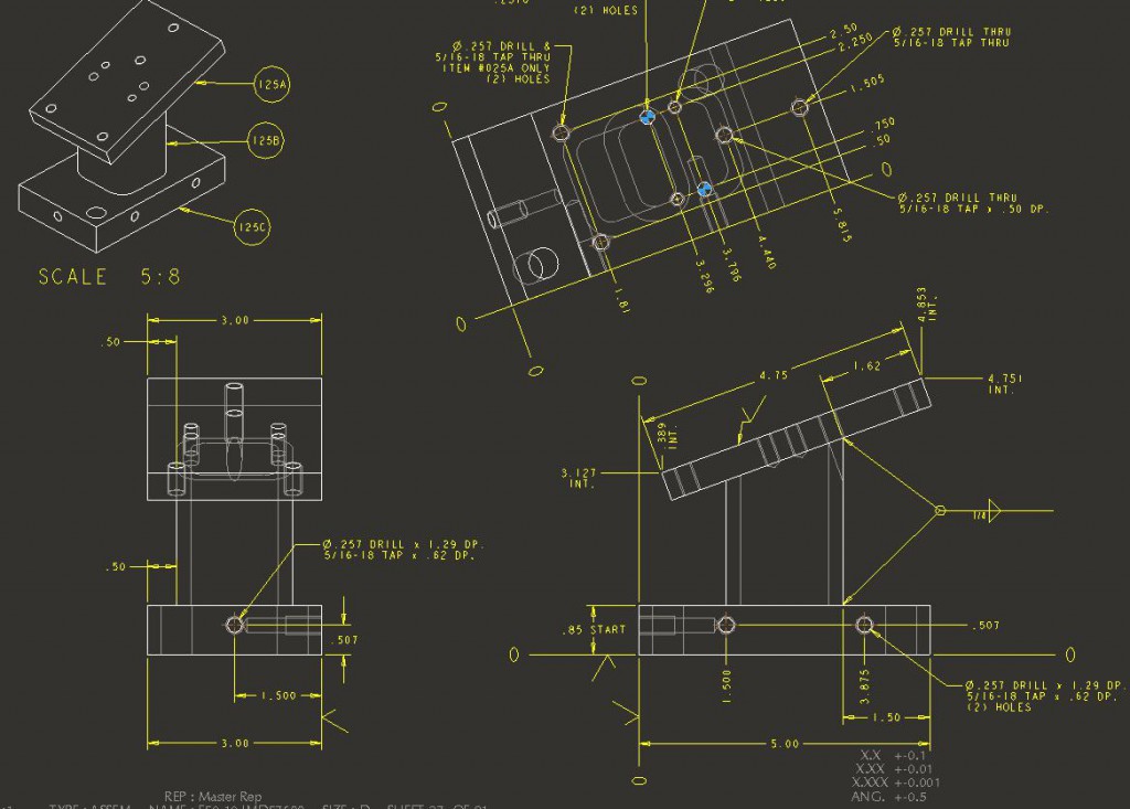
Some companies dimension from the edge of the Angled Surface. This is NOT a good practice when the features on that angled surface are critical. (Meaning their location needs to be within a small tolerance range from the features that are not on the angled surface.)
If this is your company standard, and you have a situation needing precision, then question authority, talk to the shop that is going to be making the part and see how they would like you to do it.
Some companies dimension from the zero-zero corner even if it isn’t near the surface of the angled cut such as shown in this example.
Some companies dimension from a construction hole.
A construction hole is simply a dowel hole that is created to be a starting point for all other feature dimensions. The angled surface is dimensioned from the construction hole as well as all other features in the part.
Each company has their reasons for dimensioning like they do. Maybe they just do whatever is easiest for their CNC operator. Maybe they are sticking to old methods because that was the way it was done in the past
When you are starting out, learn your company’s standard first. Then, you can dig into the why and maybe offer some improvements.
Pro/E and Creo classes now online.
And LOOK HERE! I shouldn’t be instructing Pro/E anymore since you can learn it online cheap…. if you live in California. Here’s what Marvin from PTC/CREO tells me:
“These classes are taken entirely over the web and do not have any on-site requirement.
For California state residents, the current junior college tuition is $36/unit.
With book (student software is typically provided at no additional charge) and additional bogus fees, each one of these distance learning classes will cost approx $150-$200 total (Cal State resident only).
A bargain price for learning a useful skill from one of the best CAD instructors in the USA.”
De Anza College – Computer Aided Design and Digital Imaging
Distance Learning CAD Classes
6 Week Summer Session Starts July 2
http://www.deanza.edu/cdi
CRN Crs Sect Title Instructor
01215 D070D 61Z PRO/ENGINEER WILDFIRE (BEG) Lamit, Gary
10586 D070E 61Z CREO PARAMETRIC (BEG) Lamit, Gary
01031 D071D 61Z PRO/ENGNR WLDFR (INTERMED) Lamit, Gary
10588 D071E 61Z CREO PARAMETRIC (INTERMED) Lamit, Gary
01032 D072D 61Z PRO/ENGINEER WLDFR (ADV) Lamit, Gary
10590 D072E 61Z CREO PARAMETRIC (ADV) Lamit, Gary
Most of the required CAD software is available as a free download to enrolled students.
What they won’t teach you is… machine design.
For example, how to dimension angled surfaces like we talked about today!
So if you want to learn more about machine design, sign up for education and updates on the weld fixture design 101 web site. Once you sign up you will receive an email notice when the next educational blog is posted.
Til then,
The Queen
PS
For fun, check out this new way to skate board without a board.


